Yesterday, I open up my Altec Lansing ATP3 again to capture what I have done for my ATP3. In this post, I will share out how I modified my Altec Lansing ATP3. Actually the modification I done last year and now only posted it. Reason being, that time I don't have camera to snap on it.
*REMINDER...MODIFY AT YOUR OWN RISK...


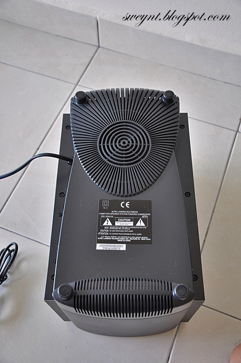
To open the circuit board, you have to remove the screw on bottom of the woofer (picture above). The board is stick on the plastic. Be cafeful when open it up.

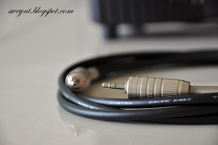
This is my DIY cable to replace the stock cable. The material that I get from Jalan Pasar . I bought 2m of Canare cable(L-2T2S) and 2 of Canare 3.5mm jack(F-12).

This is what you can see after open out from the woofer. It sticked on the plastic.Be careful when remove the plastic from the woofer. There are some wires connected.
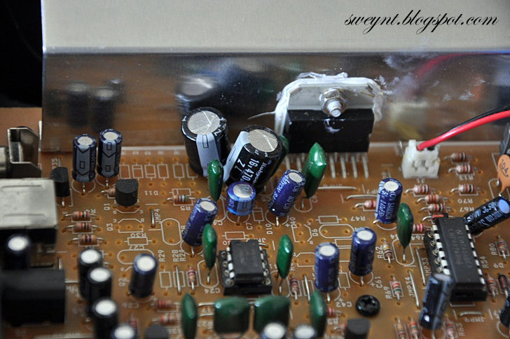 I changed the output capacitor with Rubycon ZL series.(16V 470uF). I noticed that there is different, the sound is clearer that before, more background sound.
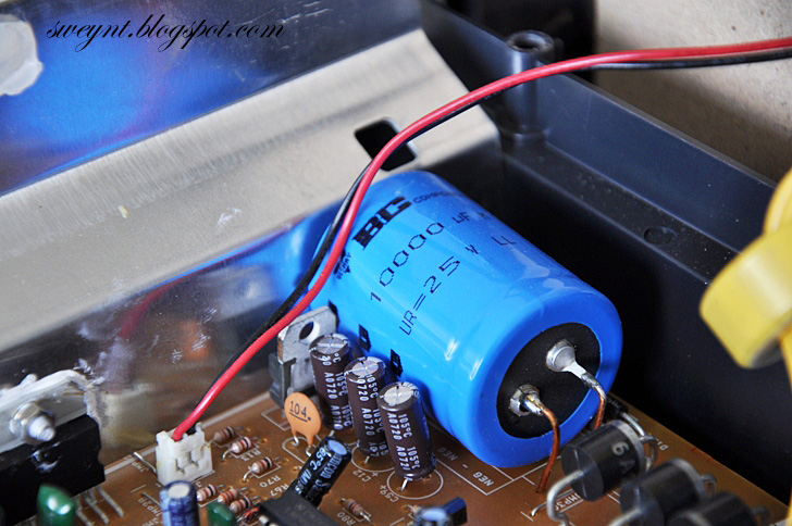 There is one big capacitor which I replaced with BC Component capacitor of the same value &voltage. 25V 10000uF. This capacitor is used for smoothing out the DC after the reactifier circuit. The characteristic of the capacitor is low ESR value and high rippler current. The reason why I changing this is because a clean DC able to produce with clearer sound.
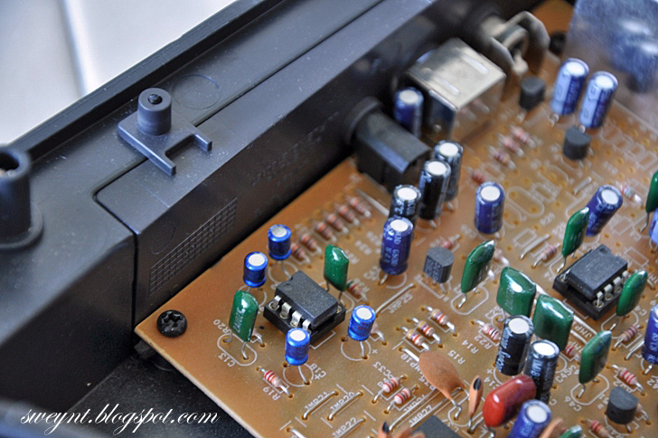 In my ATP3, it initially has 3 Dual Op-amp(ST4885). It was replaced with LM4562. Originally the ST4885 is soldered through the board. You have to de-solder it and adds in the IC socket(8 pins) so that in future if you want replace to the op-amp, you may easily plug and plug.
Besides the op amp, I also changed the capacitors which near the op-amp with Panasonic ECA series.(same value &voltage).
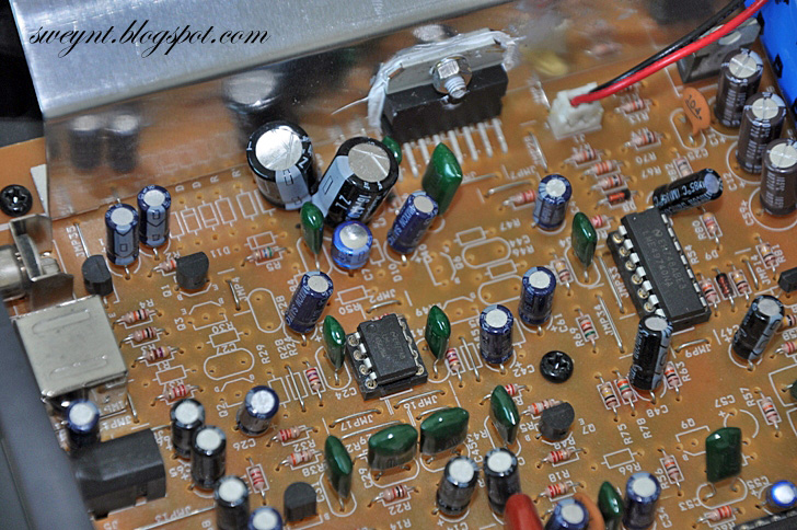 There is another op-amp located near to the power amplifier IC.(TDA7377).
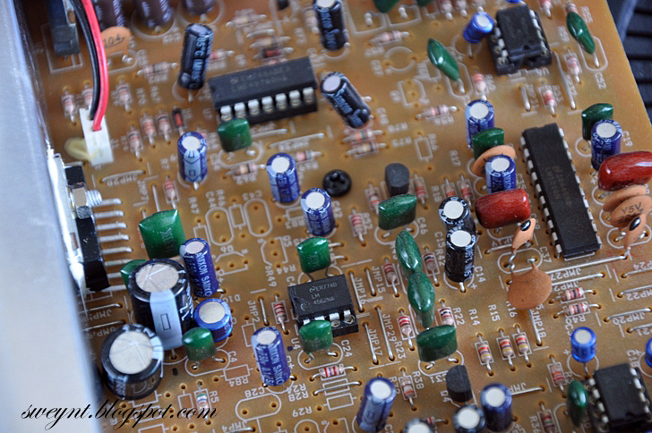
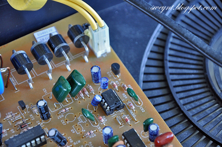 This is the last op-amp you can see from the picture. It also has been replaced with LM4562.
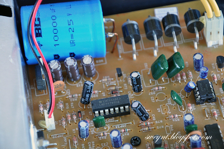 You also see one Quad op-amp(14 pins), I am not sure the exact function of the Quad op-amp, but just replace with LME49740.
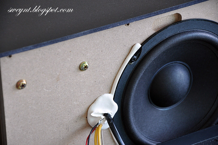
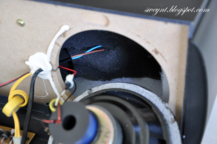 In the woofer box, some sponge was inserted to reduce some reflection wave from the wall of speaker.
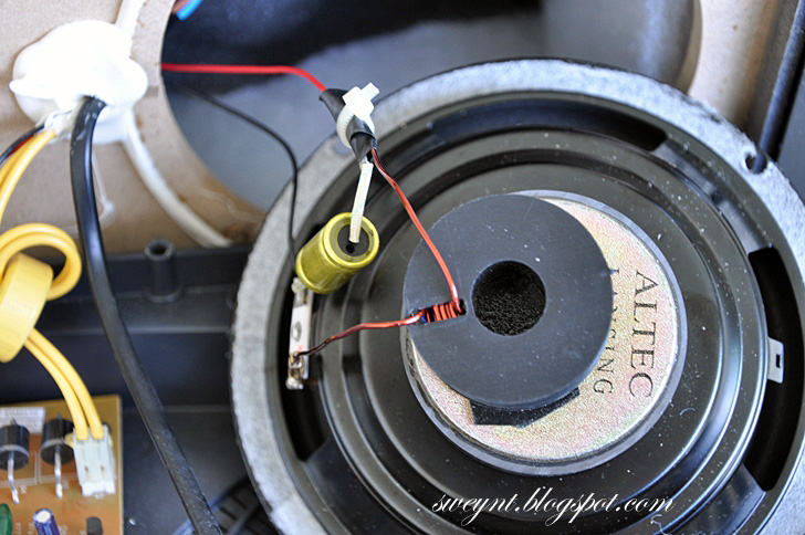 For woofer speaker, I add on one hand-made coil and one capacitor. The bass become more "solid" and strong.
 Finally, the modification is done. I test it....WOW....the sound is impresive....is clearer, separated..warmer....the bass more solid...
*REMINDER...MODIFY AT YOUR OWN RISK...

Added in photo with marking in red box.


nice job brother !!
ReplyDeletehi Yellowtail,
ReplyDeleteThanks for viewing my blog and give comment...
Is a simple ATP3 mod..hehe.
Hi, my speakers wire is broken, a rat bit the 7pin mini din conector, I got all the pins, from both sides, but I do not know wich wire is from each other.
ReplyDeleteHi Maria,
ReplyDeleteThanks for viewing my blog.
I am not very sure which connect to each other.
Anyway, you can use multimeter to trace the wire.
Is there any color at the wire?if yes, you may connect it back based on the color :P.
No, the colors does not coincide, wire is totally broken. I restored all the wire, but I do not know which wire is from each other :s
ReplyDeleteI liked your blog is very interesting.
Hi :D
ReplyDeletecan you make a markings on the components to change and also a simple how to install? :) thanks
hi Jerome,
ReplyDeleteThanks for viewing my blog.
I already marked on the component with in red box. kinldy see the last picture.
I use the soldering gun to remove the original component and replace with new component.
For the IC part, I add on the IC socket so that in future I can easily remove and plug with another IC.
Thank You! I revisited after a long long time.
Deletehi, i have had this same model for years and only one of the desktop speakers has worked. i changed win amp to play mono mp3s so i just dealt with it, but now i am moving and cant decide if i should throw these speakers out or not. any suggestions?
ReplyDeleteChristopher, If you should want to part with an ATP3 system... I'm interested.
ReplyDeletehi Christopher,
ReplyDeleteIf you like your ATP3 much, I hope you keep it..If you decide to throw, is better give to others that might be intrested it.
hi sweynt thank so much i modified my own ATP3 but i was little bit confused with the capacitors There is one big capacitor which I replaced with BC Component capacitor of the same value & voltage. 25V 10000uF. the small ones beside it. what is the value? based on the redmarkings that you made it was a little bit confusing. :(
ReplyDeleteExcellent posting! Christopher- my left channel quit working; removed the board, used a multimeter and found the solder connections were 'cold soldered'. Re-soldered the connections, re-assembled, and all's well.
ReplyDeletehye sweynt..i'm very happy if you can help me out..nice blog you have btw..
ReplyDeleteso here it is,i own 3 sets of ATP3..my first set did not produce any bass,just heard from the treble unit..if i were to replace parts,which segment should i try first?
and 2nd Q is,how much is the cost for all the electronic parts you replaced?
mind you,i'm not electronically trained,more on mechanical,but i do know how to use solder,heatshrink etc..i had dismantle my ATP3 after it was broken but then i just sit there and look at the circuit..LOL..
thanks in advance
the amplifier ic is TDA7377 not TDA7375 ?
ReplyDeleteWow! very interesting mod! After reading your article, I also wanted to do what you did but, unfortunately, I am not electronically inclined. Anyway, I always had this weird idea of using my 8-yr old atp3 as car audio system. Do you know what voltage is the transformer inside? is it from 12v? If it is, I think we can bypass the transformer and connect it directly to car battery which is also around 12v. I would be more grateful if you could tell/show me how. Thanks. Great blog!
ReplyDeleteYes! Beyond that bridge of diodes.
Deletewow very interesting modification....
ReplyDeletei wanna know about the hand made coil that you add to the subwoofer... can you explain that..??
thanks for your answer
Good day!
ReplyDeleteI just want to know if you have schematics with this model because I have an ATP-3 that have symptoms of broken sound output after minutes of playing but still power led on is ok. please email me if you have thanks
I have the same problem.
Deletenice work
ReplyDeleteI have a the same system that a friend asked me to sort out for him so you have a pin-out diagram?
Where is wire diagram for ATP3 speaker to the Circuit board.
ReplyDeletePlease email me the ATP3 diagram, as my unit also have broken output, anyone can advice what is the possible cause?
ReplyDeleteHi, I have one question, I have only subwoofer as I connected to the Computer and controlling sound Bass?
ReplyDeleteDid you tried to make a headphone output?I want to make one embeddeb in the woofer housing.Can I do that only connecting to the board inside the woofer?
ReplyDeletebro... please help me
ReplyDeletehow to open box/cover speaker vocal
i want to change potensio volume
but i cant open that cover..
please....
hello Wesly....
ReplyDeletethat box is fixed with gum, so broke it carefully.....
Could anyone check witch pin from the female 7 pin connector on the subwoofer corresponds to whitch connection on the circuit board in the right speaker?
ReplyDeletewhere do i get a new circuit board for ATP3's? I dont want to let mine go...
ReplyDeletei want to talk to you mr sweynt
ReplyDeleteplease give me details about the filtering capacitors used in this circuit board of ATP3....
ReplyDeleteCan you tell me the schematics of the 7pin miniDIN connector?
ReplyDeleteI hope you had googled it! There are good pics to teach you on that.
DeleteHi just a question : I have ATP3 2 systems and they both do't filter well the 60Hz from network. As a consequence, there is a constant deep sound in the speakers. I see there is no ground on the schematic. Would any of you have an efficient solution for this? Any way the wire a ground on the circuit? Thanks !
ReplyDeletehey there, can you help me with atp3 transformer. what is the rating of the tranformer for atp3? mine got busted, please give details thanks..
ReplyDeleteI am also facing the same problem.
DeleteCould you check witch pin from the female 7 pin connector on the subwoofer corresponds to whitch color wire on the cable of the right speaker?
ReplyDelete@ralfe baricaua & prok, atp3 transformer is 12volts
ReplyDeleteHello,
ReplyDeletei have ATP3 but i am facing the same problem that main woofer is not produce sound i thing it have some circuit problem kindly tell me where to find the same circuit ?
hello hi anybody want to sell good condition ATP3 to me? i want to buy
ReplyDeleteHi.. do you know how can i fix the cable of my atp3,. the cable of the speaker that has the volume treble and bass..it has a 7 pin mini-din cable. twas cut into two.. is there a way i can reconnect it?
ReplyDeleteYou mean 4558 amps, not 4885?
ReplyDeleteanybadi ??? 7pin... colors ?
ReplyDeleteI had a problem with the left speaker cutting in and out. I took apart the subwoofer, and saw that the solder was cracked. Redid the solder, now the left speaker works. However, I hear subwoofer hum now whenever it's turned on. The amount of hum does not depend on volume. However, if I move the circuit board away from the subwoofer, the hum goes away. Any idea what I can do?
ReplyDeleteThanks,
Greg
Hi, I have a problem with the right satellite, power LED always keeps switching on and off. Do you have any idea how to solve this? Also, the sound of the speaker turns on and off when the LED switching on and off. I really appreciate if you can help me to solve the problem. :)
ReplyDeleteHi, I have a problem with the right satellite, power LED always keeps switching on and off. Do you have any idea how to solve this? Also, the sound of the speaker turns on and off when the LED switching on and off. I really appreciate if you can help me to solve the problem. :)
ReplyDeleteI have the similar problem, anyone knows how to resolve?
do you ahve a video tutorial for this? It will help a lot. I like your mod
ReplyDeleteHi
ReplyDeleteI just opened mine to see if I can find any bulging capacitors. I did not find any. Mine is making noise even if you don't have it plugged in to the TV or laptop. when you turn on the knob on the speaker its ok until i hit 12:00 on the knob then its a loud noise. Tried different outlets even took it to work and tried it there. Still same problem loud noise. I to like these speakers. Mine is like new out of box. Any help on this? Maybe I can send you my main board and you can repair it and send it back. i can send with prepaid postage. I can pay for all the parts. Let me know. Thanks. :)
How many round u make the coil? How thick is ur coil? And how big the diameter of ur coil?
ReplyDeleteThis comment has been removed by the author.
ReplyDeleteI HAVE A ATPL 3 MINIDIN MALE PIN CONNECTOR PROBLEM, I WANT TO REPALE THE CONNCECTOR PLEASE HELP BY PROVIDING COLOR CODE IN THE CABLE AS MENTIONED,
ReplyDelete1. RED
2. YELLOW
3.ONLY ALUMINUM WIRE
4.RED
5.GREEN N GOLDEN
6.ORANGE
7.RED WITH GOLDEN
8.BLUE
9.GREEN
PLEASE HELP AS WITHOUT THE SAME CONNECTOR THIS SPEAKER SYSTEM IS OUT OF ORDER, PLEASE HELP
You can refer to https://dennyhermawanto.wordpress.com/2013/08/02/altec-lansing-atp3-satellite-speaker-mod/
DeleteI modded my atp3 with ne5532 n nichicon caps....sounds good now.
ReplyDeleteOne question about the passive crossover for the sub. What value did you use for the coil?
My next test is to upgrade the filter caps with a 15000uf to see if it get gets any better with the bass. Will keep posted.
Hi,
ReplyDeleteI have same ATP3 with me and my right Satellite audio is not there, everything works from, treble /bass, on/off subwoofer and left satellite speaker, What could be wrong in this case. Being amateur with circuits wanna try myself fixing it.
Please help me with it.
I have same ATP3 north american model 120v/60Hz/120w. Power supply in subwoofer
ReplyDeleteis missing. I don't know what AC voltage is applied to main connector on PCB. Europeen model specify 12v ac @ 3.5A. Do you know the exact spec for my model ?
Excellent job (& the finest pics)
ReplyDeleteBy the way, I reached your blog by following ALL I could surf to get info on Altec Lansing SubWoofer ACS340 schematics... I had the hunch your pics were copied and I reached this point.
DeleteThanks!
A mechanic has wrongly changed the original transformer of my Altec Lansing ATP3 multimedia speaker system and now the woofer and speakers are not working properly. I want to know the correct specification as output volatege and amperes for original transformer of Altec Lansing ATP3.
ReplyDeletesame is here sir.... please let me know this when you would know.... please... or let me know where from i can get original transformer... my mail is--apurbaroybahadur@gmail.com... please sir.. answer me.. thanks..
Deletelet me know where from i get the original transformer of altec atp3... please ... or let me know the full specification of the transformer... like volt/amp etc... thanks
ReplyDeletei will like to get a diagram
ReplyDeleteHi. I have same model but...why? The fuse always blow everytime I switch on the power?? Now i have dozen of blowed fuse 😅
ReplyDeletewondering of the coil to subwoofer... detailing please
ReplyDeleteHallo, pls help me if any one have wiring diagram/remark to identify pin 8 for altec lansing atp 4 or 5, many thanks
ReplyDeleteHello, I allow myself to contact you because I am also looking for the diagram of the mini DIN 8 pin connector for ATP5 Altec Lansing, if you have the scheme and son colors, thank you kindly to communicate them to me. Mine everything works but I do not I do not have the on / off of the subwoofer. I give you the colors by starting (2 pins down) anti-clockwise. Tell me what's wrong, with all my thanks. red - red and gold - red and red green - 4blue and gold - 5 green - 6 blue - 7 green and gold - and medium big gold thread
DeleteI have subwoofer but i don't have speaker if possible please give me 2 speaker of altec lansing atp3 control
ReplyDeleteWhere can I get this board, as i have damaged the board.
ReplyDeleteAuthor has kept superb unknown ideas, that will help most of music lover. It is not only includes huge ideas but also user friendly with figure-out post. If anybody read this article will reinforce to get this. Thanks a million for this post.
ReplyDeleteGood Day Sir Sweynt!
ReplyDeleteSame Speacker
Lwft channel not working!
Already check cable and wiring
Working!
Still not working,
Please help!
Thank you
I need this board. Can you pls the cost of board
ReplyDeleteMy APT3 works for a few seconds and sound disappear. It could be a bad capacitor and I do not know which one? Where can I get a new amplifier board?
ReplyDeleteI need the ATP3 service manual.
ReplyDeleteSpeaker subwofer saya tidak berfungsi tolong beritahu di mana letak kerusakanya
ReplyDeleteWho can sell me ATP3 right side(with control) satellite, my one wire bitten by a rat..
ReplyDeleteI want to sell complete set which is working condition
Deleteif APT3 works for a few seconds and sound disappear.( green LED not glowing ) It could be due to bad contact by Micro switch near volume control nob PCB in side of satellite speaker. staellite speaker can be opened by a set of flat sharp edge screw driver ( two nos ) carefully in small steps. clean micro switch with Iso propyl alcohol or equivalate. if still problem then resolder its pin on PCB side. i can send you image and video of the same. If required.
ReplyDeleteMr Onkar does ur problem solve because I also facing same problem
ReplyDeletevery inspiring....i have one will to try someday
ReplyDelete